
In this article
Common temperature-sensing approachesThe hidden importance of placementThermistors, RTDs and thermocouplesMeasurement error and self-heatingWhat a temperature reading cannot revealSensor placement and time lagQuestions readers often askAre thermistors digital sensors?Does a fast sensor eliminate temperature lag?Explore related engineering topicsReferences and further readingRelated articles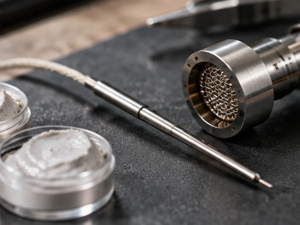
Temperature sensors turn a physical temperature-dependent property into a signal a controller can interpret. The choice of sensor, its location and the measurement electronics all affect how faithfully the reading represents the region of interest.
Common temperature-sensing approaches
An NTC thermistor changes resistance as temperature changes. Resistance temperature detectors use the temperature dependence of a metal's resistance, while thermocouples produce a small voltage related to a temperature difference. Some devices use integrated semiconductor temperature sensors. The different approaches have distinct ranges, costs, response times and calibration needs. The presence of a given sensor type does not, by itself, guarantee chamber accuracy.
The hidden importance of placement
A sensor attached to the heater can react quickly to heater temperature but may not describe conditions elsewhere. A sensor further from the heater might track a chamber surface more closely while responding more slowly. Heat flowing through wires, adhesives and structural parts can also influence a contact measurement. Engineers therefore specify not just a nominal accuracy but the location and conditions under which that figure applies.
Thermistors, RTDs and thermocouples
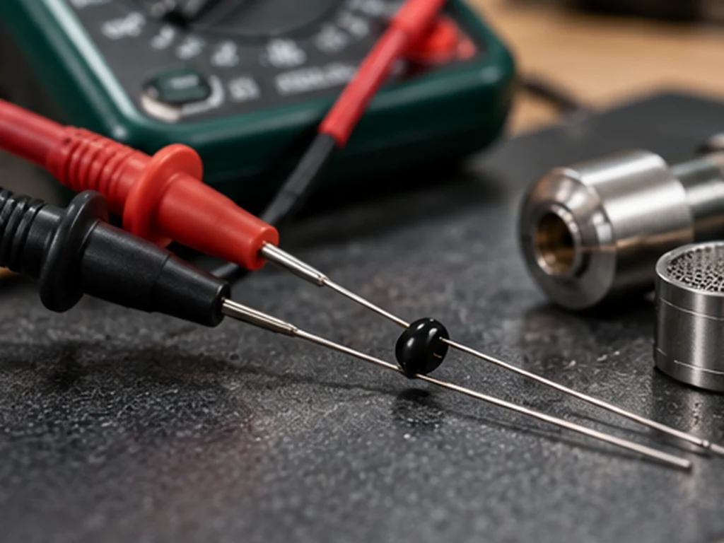
Common temperature-sensing technologies trade off sensitivity, range, linearity, mechanical size and cost. A thermistor changes resistance strongly with temperature, an RTD uses a more controlled resistance relationship and a thermocouple generates a voltage between dissimilar conductors. Electronics convert those signals into estimated temperatures. Each approach requires appropriate calibration, wiring and placement; a sensor's existence is not proof that the final device reads accurately under all operating conditions.
Measurement error and self-heating
A thermistor is read by passing a small current through it. That current dissipates energy, so excessive measurement current can warm the component and introduce error. The analogue-to-digital converter, reference components and calibration algorithm contribute further uncertainty. Environmental changes and ageing may alter the result. A useful specification separates the sensor's data-sheet tolerance from the accuracy of the entire installed measurement system.
What a temperature reading cannot reveal
A single sensor cannot resolve the complete three-dimensional temperature field inside a chamber. It may be entirely adequate for a controller's design goal while being unsuitable as a laboratory measure of the material or aerosol. Readers should check what is actually being measured before relying on temperature claims for product comparisons.
Sensor placement and time lag
A probe buried in a metal heater reacts differently from a probe suspended in air. Thermal contact compounds, insulation and the probe's mass can slow its response. When a system heats rapidly, small delays can create meaningful differences between a display and the surface you actually wish to measure. A credible test checks sensor accuracy and response under representative transients, not only at a stable room temperature.
Questions readers often ask
Are thermistors digital sensors?
A thermistor is a temperature-sensitive resistor; a controller usually measures it through an electronic circuit.
Does a fast sensor eliminate temperature lag?
No. Physical heat transfer between the point of interest and sensor may still introduce delay.
Explore related engineering topics
- Vaporiser Technology & Engineering
- How Vaporiser Temperature Control Works
- Measuring Device Temperature: Surface vs Chamber
References and further reading
- Analog Devices — Temperature sensing engineering resources
- NASA Glenn Research Center — Heat Transfer
This guide explains engineering concepts, not the safety, emissions profile, legal classification or performance of a particular product.