
In this article
What counts as heat-up time?Why thermal mass changes the timelineHeat-up time requires a defined endpointUnderstanding stability and recoveryHow to evaluate performance statementsThermal stability is dynamicQuestions readers often askCan a device be fast but thermally unstable?Why might the same device warm up differently twice?Explore related engineering topicsReferences and further readingRelated articles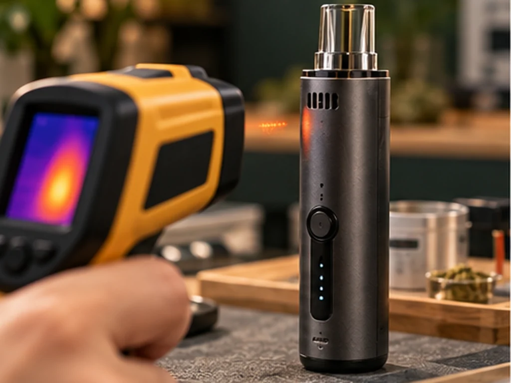
Heat-up time and thermal stability are two different aspects of heating performance. The first concerns how a device approaches an operating condition; the second concerns how its temperature behaves once operating. A short warm-up claim alone does not tell the full story.
What counts as heat-up time?
Manufacturers may define warm-up from the moment power is enabled to the moment a sensor reaches its setpoint. Others may count from a user command to a visual 'ready' signal. Neither definition necessarily means every part of the chamber has reached thermal equilibrium. A comparison only makes sense when the starting conditions, target, sensor location and completion criterion are stated. Ambient temperature and recent use can materially affect the measured interval.
Why thermal mass changes the timeline
A larger or heavier heated component generally takes more energy to raise its temperature by a given amount, other things equal. A well-coupled heater may transfer that energy efficiently, whereas losses to the surroundings consume additional power. Once warm, a thermally massive component may respond more slowly to disturbances. A compact, low-mass part can warm quickly but may also cool faster when additional air passes through it.
Heat-up time requires a defined endpoint
A manufacturer might start the clock when the user presses a button and stop it when the display reaches a setpoint. An independent test might stop when a chamber probe stabilises. Those endpoints are not equivalent. A rapid setpoint indication may reflect a small sensor mass while the full assembly is still warming. To compare heat-up times, specify the start conditions, supply power, endpoint, sensor position and test repetitions.
Understanding stability and recovery
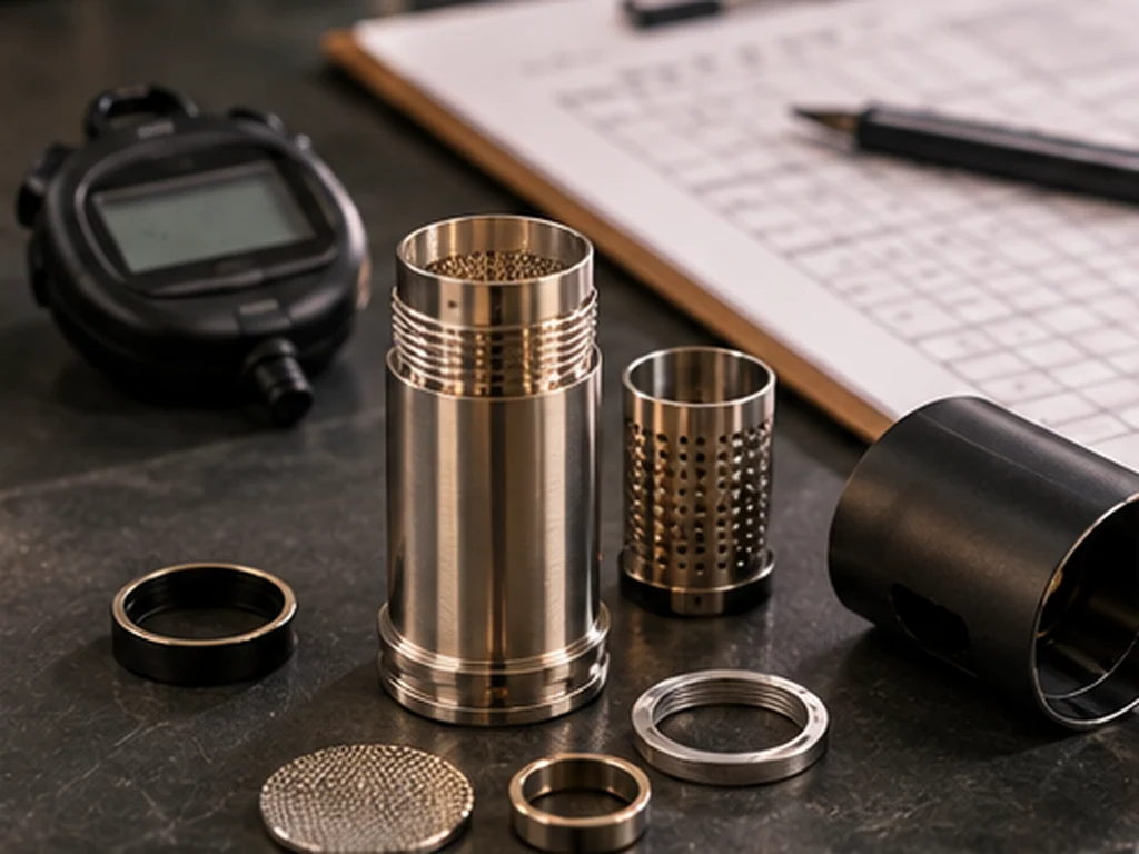
Thermal stability concerns fluctuations around an intended operating condition. Recovery describes the system's response after a disturbance, such as a change in airflow or a cooler component entering the system. Engineers may assess overshoot, undershoot, settling and steady-state variation. A stable reading near one sensor does not imply zero variation at every location. Test descriptions should state whether measurements concern the heater, chamber wall or flowing air.
How to evaluate performance statements
Avoid ranking designs solely by a quoted warm-up duration. Look for the measurement method, repeated trials, duty cycle, energy consumption and control behaviour under changing conditions. The fastest system is not necessarily the most accurate, efficient or suitable for any particular intended purpose. Clinical and inhalation-safety claims are separate questions requiring appropriate evidence.
Thermal stability is dynamic
Stability is not simply a flat line during idle operation. Opening a chamber, changing air flow or adding a cooler load can disturb the balance. A good test records recovery time, overshoot and how much temperatures vary during a standardised cycle. Devices with substantial thermal mass may recover differently from lightweight heaters, but the result cannot be inferred from size alone.
Questions readers often ask
Can a device be fast but thermally unstable?
Yes. Reaching a target quickly does not guarantee minimal fluctuation afterwards.
Why might the same device warm up differently twice?
Starting temperature, ambient conditions and recent operation can change the result.
Explore related engineering topics
- Vaporiser Technology & Engineering
- How Vaporiser Temperature Control Works
- The Role of Thermal Insulation in Device Design
References and further reading
- NASA Glenn Research Center — Heat Transfer
- Analog Devices — Temperature sensing engineering resources
This guide explains engineering concepts, not the safety, emissions profile, legal classification or performance of a particular product.